Before we start, backup configuration:
copy running-config scp://<user>:<password>@<scp_ip>/path/running-config.txt
Before starting the LC installation, we must make sure that all switches are at the same NOS (Network Operating System) level.
You should be careful that it is the most stable version instead of the latest NOS version. I preferably use the latest Target Path version on new installations.
If you are going to install a couple of VDX switches, it is best to install from USB. If you do not have a Brocade USB, you can start the NOS update by configuring the management IP.
usb on
firmware download usb dir nos6.0.2b coldboot
usb off
If you do not have a USB, you can install the firmware using the command below.2
firmware download interactive
NOTE:
If you did the NOS update using FTP/SCP, reset its configuration before doing the last VCS LC. VCS LC structure acts as a single switch at L2 level and its configuration is unique. Therefore, switches with different configurations cannot be included in the VCS structure, in this case you will see a conflict message.
In case you see a conflict message, reset the configuration. Restart the system.
switch# copy default-config startup-config
This operation will modify your startup configuration. Do you want to continue? [Y/N]: Y
switch# reload
After NOS is updated, let’s start the installation.
While all switches must be in the SAME VCS domain (VCS-ID) within the VCS, they must have DIFFERENT RB-IDs. Since RB-IDs are used in TRILL, they must be unique within the VCS domain.
You know, Broadcast, Multicast packets are the reason for loop. FSPF creates a Multicast Root Tree (similar to Spanning Tree) to avoid looping. Multicast, Broadcast and unknown unicast traffics are transmitted through this tree.
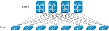
See. Spine Leaf Architecture.
Multicast Root Selection becomes important in large networks. One of the spine switch should be preferred as a Multicast Root switch . Actually, there is no such requirement, but as you grow your network, you may encounter problems because of the multicast tree. The Multicast Root switches can be set manually by entering the priority (Multicast Root with a higher priority is selected, the default is 0.) It can also be set by selecting the RB-ID of the Spine switch.
fabric route mcast RBridge ID <RB-ID> priority <priority>
The Multicast Tree may change in the following scenarios:
1) Root switch exits or down from VCS
2) If all paths to Rbridge close to the root switch are down
3) If the priority of one of the rbridges is increased.
To install the VCS, we enter the following command. You do not forget that the VCS field number must be the same for all switches, the Rbridge number must be unique in all VCS.
Command:
vcs vcs-id <vcs-id> rbridge-id <rb-id> logical-chassis enable
After typing this command, the system will be reloaded and when the physical connections are made, the switch will be included in the VCS structure.
After the switch is turned on and the physical connections are made, the ISL connection and its status in the VCS are checked.
Sample Output:
VDX01# show fabric isl
Rbridge-id: 1 #ISLs: 3
Src Src Nbr Nbr
Index Interface Index Interface Nbr-WWN BW Trunk Nbr-Name
——————————————————————
11 Te 1/0/4 3 Te 2/0/4 10:00:00:05:33:67:AF:3C 10G Yes “VDX02”
31 Te 1/0/24 23 Te 3/0/24 10:00:00:05:33:4A:D1:C4 10G Yes “VDX03”
VDX01# show vcs
Config Mode : Distributed
VCS Mode : Logical Chassis
VCS ID : 101
VCS GUID : 6dfb82a4-bbb7-4257-9a2f-51e384321a6e
Total Number of Nodes : 3
Rbridge WWN Management VCS Fabric HostName
-Id IP Status Status
——————————————————————-
1 10:00:00:05:33:DE:C3:35 192.168.8.191 Online Online VDX01
2 >10:00:00:05:33:67:AF:3C* 192.168.8.192 Online Online VDX02
3 10:00:00:05:33:4A:D1:C4 192.168.8.193 Online Online VDX03
The “>” sign here indicates that it is the principle switch, and “*” indicates the connected switch.
VCS is a masterless architecture. There is no manager. Principle switch has some responsibilities unlike other switches. Since these responsibilities do not affect the operation of the all switch fabric. To change the principle switch does not cause any interruption or change in the structure.
Principle Switch:
When all switches are opened at the same time, each switch is opened as “I am principle switch”. They make an effort to become a principle. In this elimination, the principle switch with high priority is selected, if you do not configure priority, the default is the same for everyone, the principle switch with the low WWN address is selected.
As for the responsibilities of the principle switch:
1) Checks whether the new Rbridge to be included in VCS has conflicts. For example, a switch with the same Rbridge ID cannot be included in the VCS, it is controlled by the Principle switch.
2) The configuration is distributed to all other switches in the VCS with the principle switch.
Changing the name of the switch:
sw0# configure terminal
Entering configuration mode terminal
sw0(config)# switch-attributes 1
sw0(config-switch-attributes-3)# host-name VDX01
OoB Management Settings:
Switch management settings must be made. Configure as following.
Sample:
interface management 1/0
no ip address dhcp
no tcp burstrate
ip icmp unreachable
ip icmp echo-reply
ipv6 icmpv6 unreachable
ip add 192.168.10.11/24
rbridge-id 11
vrf mgmt-vrf
address-family ipv4 unicast
ip route 0.0.0.0/0 192.168.160.1
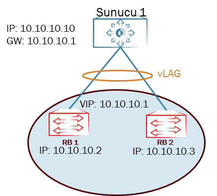
After the Management IP address is set, you must also set the virtual IP address. The virtual IP address is assigned to the principle switch and the principle switch will always respond to this IP address. Thus, you will be able to configure the switch with this IP address. Below 192.168.10.10 is our virtual IP to manage VCS cluster.
vcs virtual ip address 192.168.10.10/24
In Band Management:
If you do not use OoB management, you can also access any vlan by assigning an IP. My preference is always to access via OoB management.
int vlan 100
Desc Management Vlan
rbridge-id 1
interface ve 100
ip 192.168.10.11/24
vrf forwarding mgmt-vrf
rbridge-id 1
vrf mgmt-vrf
address-family ipv4 unicast
ip route 0.0.0.0/0 192.168.10.1
Port Channel Setting:
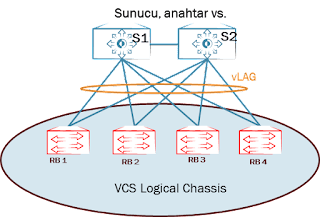
You can define up to 8 vLAG (virtual Link Aggregation Group) switches within the VCS LC structure. In the example below, I drew 4 VDX switches. Switches in VCS work like a single switch. The servers/switches I’ve drawn treat VDX switches as a single chassis switch.
Ports:
RB1 Te1/0/1 ==> S1
RB1 Te1/0/2 ==> S2
RB2 Te2/0/1 ==> S1
RB2 Te2/0/2 ==> S2
RB3 Te3/0/1 ==> S1
RB3 Te3/0/2 ==> S2
RB4 Te4/0/1 ==> S1
RB4 Te4/0/2 ==> S2
Let’s set the ports to trunk. You may have noticed that it has a very similar command set to Cisco. For Access, you can still do it like Cisco.
interface Port-channel 10
Desc VCS to Servers
switchport
switchport mode trunk
switchport trunk allowed vlan all
no sh
interface Te 1/0/1
desc Link to Server S1
no fabric isl enable
no fabric trunk enable
fabric neighbor-discovery disable
channel-group 10 mode active type standard
no spanning-tree shutdown
no sh
interface Te 2/0/1
desc Link to Server S1
no fabric isl enable
no fabric trunk enable
fabric neighbor-discovery disable
channel-group 10 mode active type standard
no sh
You can make the same configurations for RB3 and RB4.
If there is another switch instead of the server, you should enter the “no spanning-tree shutdown” command. Thus, the spanning tree will be activated on this port. Spanning-tree does not work in TRILL structure.
VRRP-E Settings:
Let look at the below topology, I configure be as follows.
rbridge-id 1
no protocol vrrp
protocol vrrp-extended
int vlan 200
interface Ve 200
ip proxy-arp
ip address 10.10.10.2/24
no shutdown
vrrp-extended-group 200
virtual-ip 10.10.10.1
enable
no preempt-mode
priority 110
short-path-forwarding
rbridge-id 2
no protocol vrrp
protocol vrrp-extended
int vlan 200
interface Ve 200
ip proxy-arp
ip address 10.10.10.3/24
no shutdown
vrrp-extended-group 200
virtual-ip 10.10.10.1
enable
no preempt-mode
priority 105
short-path-forwarding
Let’s talk a little bit about “short-path forwarding”. Let me tell you through a beautiful picture I found on the Internet.
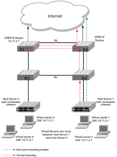
Different routers are active for different networks in VRRP/VRRP-E. So there is only one active gateway for all networks and the other one is waiting in standby.
Whichever router the server’s gateway is, the traffic is persistently directed to that router. In the example in our picture, the gateway of server1 is the R1 router, also Master one.
In the classical method, while the traffic goes to the internet by following the R4, R2 and R1 routes; By using VRRP-E short-path forwarding, the traffic will go to the internet by following the R4 and R2 routes.
NTP, Syslog, sflow, snmp Configuration:
!NTP
ntp server 192.168.11.1
!Logging to syslog server
logging syslog-server 192.168.11.12
!Setting up sflow
sflow enable
sflow collector 192.168.11.13 6343
sflow polling-interval <interval>
sflow sample-rate <rate>
int te 1/0/1
sflow enable
!Setting up snmp
snmp-server community <community-name> rw
snmp-server user <admin-name> groupname <group-name> auth md5 authpassword <password> priv DES priv-password
User/Password Creation:
You can create users in different roles. The user role has limited commands while the admin role has full authority.
username <user> password <password> encryption-level 7 role admin desc Administrator
username <user> password <password> encryption-level 7 role user desc User
You can also define your own role:
1) create a new role
switch(config)# role name newrole desc “MY-Role”
2) Let’s create a new user for this role.
username mynewuser role newrole password mynewpassword
3) Let’s create new permissions for newrole.
switch(config)# rule 30 action accept operation read-write role newrole command role
switch(config-rule-30)# exit
switch(config)# rule 31 action accept operation read-write role
newrole command rule
switch(config-rule-31)# exit
switch(config)# rule 32 action accept operation read-write role
newrole command username
switch(config-rule-32)# exit
switch(config)# rule 33 action accept operation read-write role
newrole command aaa
switch(config-rule-33)# exit
switch(config)# rule 34 action accept operation read-write role
newrole command radius-server
switch(config-rule-34)# exit
switch(config)# rule 35 action accept operation read-write role
newrole command config
switch(config-rule-35)# exit
Thus, we enabled mynewuser to configure a role, rule, username, aaa and radius-server commands at the configuration level.
Routing:
While all switches in the VCS act as a single chassis in terms of L2; In terms of L3, all switches can behave differently. So all L3 operations are done under rbridge-id context.
sw0(config)# rbridge-id 1
sw0(config-rbridge-id-1)# interface ve 50
sw0(config-ve-50)# ip address 10.10.50.1/24
sw0(config-ve-50)# exit
sw0(config)# rbridge-id 1
sw0(config-rbridge-id-1)# ip route 0.0.0.0/0 172.16.1.1
sw0(config-rbridge-id-1)# ip route 10.1.1.0/24 172.16.2.1
OSPF:
QSFP Breakout:
conf t
int FortyGigabitEthernet 1/0/49
shut
exit
hardware
connector 1/0/49
sfp breakout
do reload
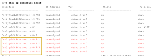
NOTE: The 1/0/49 interface is no longer visible.
Multicast Route Configuration:
Spine switches (RB1 and RB2) multicast route switch must be set.
fabric route mcast rbridge-id 1
priority 255
fabric route mcast rbridge-id 2
priority 254
fabric route mcast rbridge-id 11
fabric route mcast rbridge-id 12
fabric route mcast rbridge-id 13
fabric route mcast rbridge-id 14
